As a result, E 1 E 1 and E 2 E 2 turn out to be slightly larger for arcs that have not quite curled through 3 π 3 π rad and 5 π 5 π rad, respectively. Since the total length of the arc of the phasor diagram is always N Δ E 0, N Δ E 0, the radius of the arc decreases as ϕ ϕ increases. These two maxima actually correspond to values of ϕ ϕ slightly less than 3 π 3 π rad and 5 π 5 π rad. The proof is left as an exercise for the student ( Exercise 4.119).

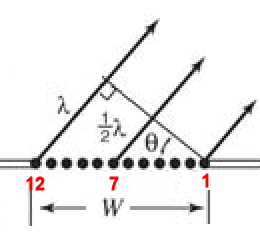
In part (e), the phasors have rotated through ϕ = 5 π ϕ = 5 π rad, corresponding to 2.5 rotations around a circle of diameter E 2 E 2 and arc length N Δ E 0. The amplitude of the phasor for each Huygens wavelet is Δ E 0, Δ E 0, the amplitude of the resultant phasor is E, and the phase difference between the wavelets from the first and the last sources is The phasor diagram for the waves arriving at the point whose angular position is θ θ is shown in Figure 4.7. This distance is equivalent to a phase difference of ( 2 π a / λ N ) sin θ. If we consider that there are N Huygens sources across the slit shown in Figure 4.4, with each source separated by a distance a/N from its adjacent neighbors, the path difference between waves from adjacent sources reaching the arbitrary point P on the screen is ( a / N ) sin θ.

To calculate the intensity of the diffraction pattern, we follow the phasor method used for calculations with ac circuits in Alternating-Current Circuits.


 0 kommentar(er)
